|

|
|

LCLS Undulator Prototype
A new prototype undulator has been designed and is
presently being fabricated for the LCLS project. The design approach emphasized mechanical
stability of the device, because stability over time is required to maintain the magnetic
tolerances. The 3.4-meter long undulator has a fixed 6-mm pole gap spacing.. A
cross-section of the undulator housing and pole structure is shown in Figure 1.
Figure 2 provides an enlarged cross-sectional view of the magnets and
their holders. Figures 3-5 are photographs of a short model of the
undulator.
Figure 1: Cross section of the undulator housing and pole structure.
Figure 2: Enlarged cross-sectional view of the magnets and their holders.
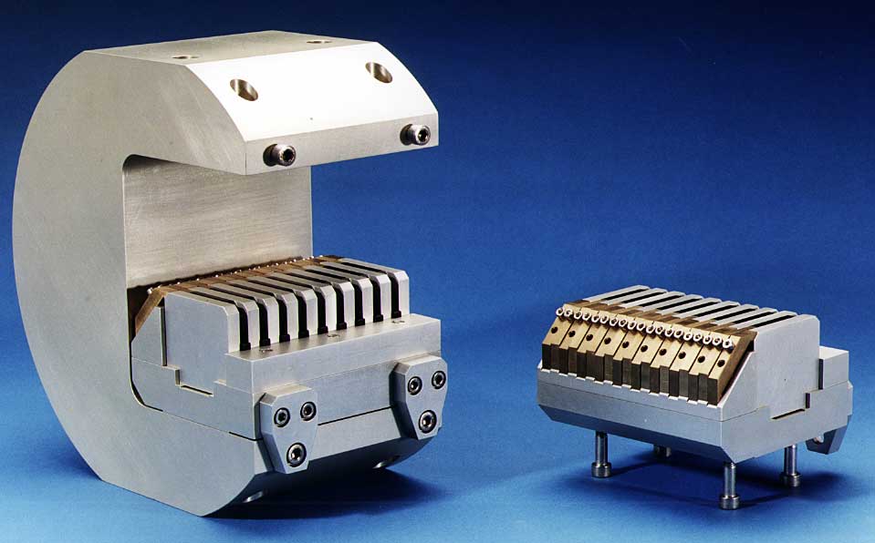
Figure 3: View of a short model (9 poles) of the new LCLS undulator
design in full assembly. The 2 times 10 aluminum colored pieces arranged in two rows are
models of the permanent magnets. They are separated by 2 times 9 pole pieces. The pole
pieces are transversely narrower than the magnet pieces. The C-shape support
structure will be made from Ti. (Click on the image to get a high resolution
version !)
Photograph: APS

Figure 4: View of the short model of the new LCLS undulator design with
the upper jaw removed from the assembly. (Click on the image to get a high
resolution version !)
Photograph: APS
Figure 5: View of the upper jaw of the short model of the new LCLS
undulator design. The 9 poles (black) and the 10 magnets (aluminum colored) are visible at
the top. (Click on the image to get a high resolution version !)
Photograph: APS
|