October through December
2000
October through December
2000
A. Project Summary
1. Technical Progress
2. Cost Reporting
B. Detailed Reports
1.1 Magnets & Supports
1.2 Vacuum System
1.3 Power Supplies
1.4 RF System
1.5 Instrumentation
& Controls
1.6 Cable Plant
1.8 Facilities
2.1 Accelerator Physics
2.2 Environmental Health and Safety
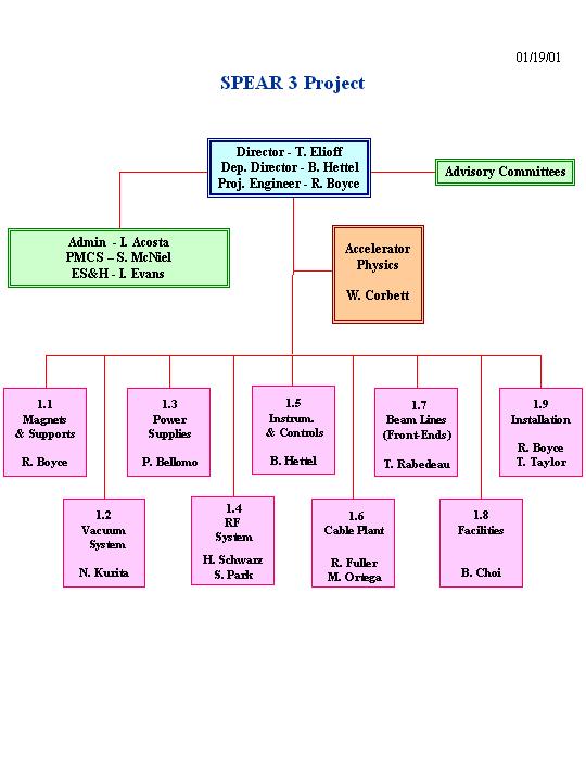
Some staff changes have occurred during this quarter as shown in the organization chart (Fig. A1). The Project Management Control System (PMCS) area is now headed by Steve McNiel who replaces Teri Knight. Teri has helped set-up the PMCS operation and reporting system over the last year and we deeply appreciate her efforts. Both Steve and Teri have the experience of utilizing the Primavera/Cobra system for tracking and reporting of the PEP-II project and we are now utilizing this system for SPEAR 3.
In the Cable Plant area (WBS 1.6), Don Martin did an excellent job heading this group to provide preliminary plans together with cost and schedule details. He is now devoting full-time for BPM systems development work in the Instrumentation and Controls areas. Management of the Cable Plant has shifted to the SLAC Controls Department. This was done in order to increase the allocated manpower and provide particular expertise in cable plant design. Leading the effort will be Mr. Robert Fuller, who becomes the WBS 1.6 System Manager. Mr. Fuller will be assisted by Mr. Mario Ortega. In addition, the participation of the SLAC Cable Group, which has been involved in SPEAR 3 since the beginning of the project, has been formalized. Also, the drafting, documentation, and Quality Control sections of the Controls Department have been formally assigned a SPEAR 3 Cable Plant role.
In the Final Installation area (WBS 1.8) headed by Richard Boyce, Tom Taylor has rejoined the group to further develop and optimize the detailed shutdown schedule for the installation process in FY 2003. A preliminary schedule was provided at the June 2000 Lehman Review. Tom planned the details and was in charge of the successful installation program for the PEP-II project.
The RF system area (WBS 1.4) has lost a significant fraction of the staff devoted to SPEAR 3 and other SLAC projects. In order to provide the required technical staff the Power Systems and Controls groups are now merged into a single Electronics and Software Engineering Department at SLAC. Engineers in the Controls area will assume responsibility for Low Level RF work such as required for SPEAR 3.
In the technical systems area, all major magnets (Dipoles, Quadrupoles, and Sextupoles) are now in production. In mid December, magnetic measurements at SLAC confirmed the IHEP measurements which indicated that the prototype sextupole (21S) is within required field tolerances and meets specifications.
The corrector magnet design was also completed this quarter. The specifications and plans are spelled out in attachment #5 of the collaboration. Seventy-five correctors will be fabricated for SPEAR 3. The detailed design of a prototype magnet support girder was also completed this quarter; the procurement award is scheduled for January.
For the Vacuum, studies were made to evaluate the type of copper to be used for the standard girder chamber. A second set of plates were machined from ¼ hard Revere copper in October. These plates were easier to machine, easier to straighten, and the final box weld had smaller deflections than ½ hard copper. A decision was made to utilize the Revere material for the larger BM1 and BM2 chambers. The shorter QFC units will continue to be fabricated with the existing ½ hard material in order to expedite the schedule.
E-beam weld tooling for the BM1 and BM2 chambers is in progress. In addition to the above fabrication of girder chambers, the designs for the RF straight section chambers were completed, the first lot of BPMs was received for test and evaluation, and the location for the Synchrotron Light Monitor was selected.
Of significant importance is the commitment of the SLAC Mechanical Fabrication Department (MFD) to SPEAR 3. In addition to piece part and subassembly fabrication of the SPEAR 3 chambers, the operations in the vacuum building require the greatest amount of oversite to insure that the chambers are completed on time and meet all technical specifications. Leo Giannini has been given responsibility for this oversite and has been assigned as MFDs Manufacturing Manager for the project.
Regarding Power Supplies, there was no response from vendors to the RFP for the main dipole supply. As a result it was decided that an in-house build of a PEP-II type bend magnet supply should be implemented and final plans are in progress. The first prototype bipolar supply will be completed in January. Work is in progress toward completing the specifications for the intermediate supplies.
Fabrication of the 4 PEP-II style RF cavities is making good progress. A new electro-forming procedure for covering the water cooling channels has been approved and the process was successfully completed on the first two cavities. The acceptance test of the 1.2 MW klystron is scheduled for February 2001 at the factory. The layout design for the waveguide system is complete. The SLAC earthquake committee has approved the design of the support stands for the Cavities and the circulator.
Work by the SPEAR 3 Instrumentation and Control (I&C) group this quarter has focused primarily on establishing an IC software development infrastructure and continuing the designs of the fast digital power supply controller, BPM processor components, and the Orbit Feedback system. The first two BPM IF digital processing modules were tested and subsequent design revisions were submitted to the vendor.
Design of the cable tray system was the dominant activity in the Cable Plant area (WBS 1.6) during the quarter. The conceptual designs, and many of the details, are well defined. Unresolved issues center on upgrading the East-West elevated cable trays, and integration of cable tray installation into scheduled yearly maintenance periods. Additionally, as mentioned earlier, management of the Cable Plant has shifted to the SLAC Controls Department, with a concomitant increase in the level and expertise of staffing.
The accelerator physics program continued software development and began on-line software testing. Efforts also included refined specifications for location and operational parameters for diagnostic components, modifications of the matching cell lattice configuration to reduce engineering costs, and studies of photon beam mis-steering through the matching cell sections. Preliminary studies for low-beta optics in the long straight were made.
Work continues on the near term radiation physics objectives
that will have an effect on this years shutdown, as well as long term goals
to comprehensively assess all shielding and design parameters, thus assuring
that respective regulations and internal limits are met. Ongoing work includes
defining what additional shielding may be required for the new C shaped
dipole magnets and minimum thickness of roof shielding for areas around
the ring.
In the last quarterly report (July-September, 2000), a
revised plan (cost & schedule) was presented which extended the SPEAR
3 project through FY 2003. This was due to the revised funding profile
for the DOE funding component planned for the project. Current funds from
NIH total 28M$ as of July 14, 2000 and 8M$ was received from DOE on November
20, 2000. According to the current schedule, these funds will carry the
project to near the middle of FY 2002. The required funding profile to
complete the project at the end of FY 2003 is provided in Table A1 below.
Table A1
SPEAR 3 Revised Plan
(M$)
Fiscal
Year
Appropriations
Obligations
Costs
1999
14.0
2.1
1.6
2000
14.0
10.3
8.8
2001
11.0
19.6
18.7
2002
9.0
16.0
18.6
2003
10.0
10.0
10.3
Totals 58.0 58.0 58.0
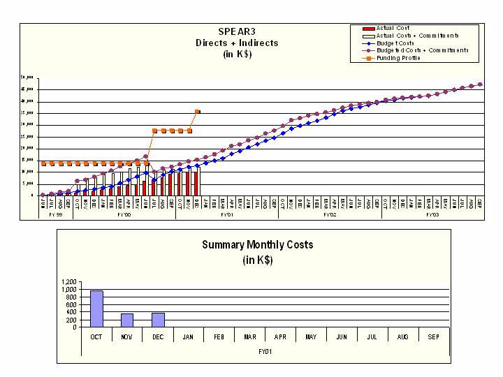
The total project costs and commitments through December
of this quarter are given in Table A2. The integrated summary
of costs and committments (planned and actual) are given in Figure A2.
Table A2
Project Costs through December 2000
(K$)
Direct plus
Direct
Indirect
Costs
9,557
10,924
Commitments 2,300
2,496
Total
11,857
13,420
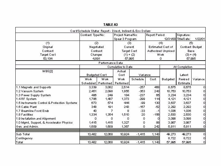
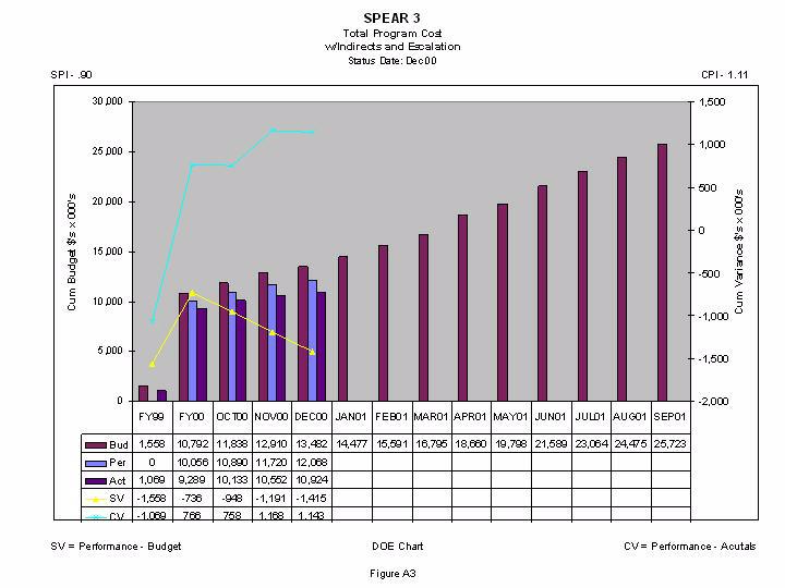
Table A3 provides the project performance data (BCWS,
BCWP, and ACWP) with associated cost and schedule variances at WBS Level
2. Monthly plots of this data for FY 2001 are provided in Figure A3 together
with BCWS projections through September 2001.
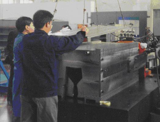
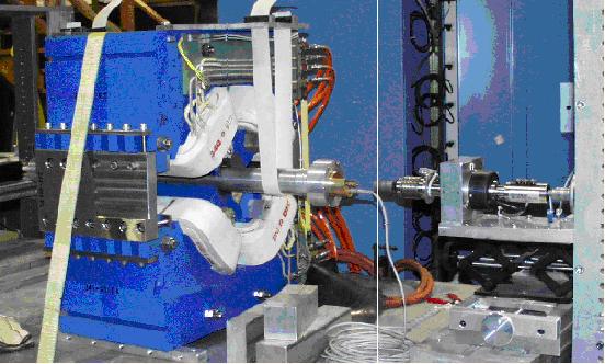
SPEAR3 Standard Cell Girder
The support system for SPEAR3 will be the fixed steel girder and adjustable magnet scheme as pictured above. This decision was made based upon the need to achieve the scheduled pre-assembly timeframe and cost considerations. A prototype fixed girder design, BM2, has been completed and sent out for quotations and fabrication. This prototype girder will be used to install magnets on struts, to finalize LCW header designs, and to check installation techniques of magnets and vacuum chamber. The order for production girders needs to be placed before August 2001 to maintain a smooth assembly process of magnets and vacuum systems.
Some progress has been made on vibration measurements of the 145D dipole magnet on struts. These preliminary results show the first resonant frequency to be approximately 15.5 Hz, which is lower then the model predicted. Further investigation into the design of the front mount on the dipole will be done to determine if this may influence the mode. Support stands for the 34Q and 21S are being fabricated to allow measurements to proceed on these magnets.
Magnets:
SPEAR3 engineers traveled to IHEP in early October to
inspect the 34Q prototype magnet along with the assembly of the dipoles
and early fabrication of the Sextupole hardware. The results of this visit
were positive with the approval to ship the 34Q to SLAC given to IHEP.
Inspection of the potted dipole coils revealed a cracking problem. This
was found to be a result of IHEP substitution of cured epoxy for G-10 filler
material. IHEP was instructed to use the G-10 filler and the cracks have
not appeared in any further potted coil. Approximately 23 coils will need
to have cracks repaired.
Inspection of the dipole core assembly was witnessed.
The injection of Devcon liquid steel epoxy has gone very well with no major
problems or issues. Inspection of the end pack pole tip machining showed
some problems that were mitigated by changing the direction of the milling
operation to prevent lifting and subsequent de-lamination. See pictures
below.
Gradient Magnet Core Assembly at IHEP
Chamfer Machining on Production Gradient Magnet Glued
End Pack
Magnetic Measurements
SLAC received the Sextupole prototype (21S) from IHEP
in early December and proceeded to complete the magnetic measurements.
The results of the magnetic measurements and other verification tests were
positive and full production approval for the 21S magnets was given to
IHEP in mid December. IHEP has been given approval to fabricate the 25S
sextupole magnet and full production will commence pending the magnetic
measurements at IHEP of the 25S first article.
Magnetic measurement results have also been received from IHEP for the 109D and 15Q magnet first articles and SLAC has reviewed these and approval given for production runs.
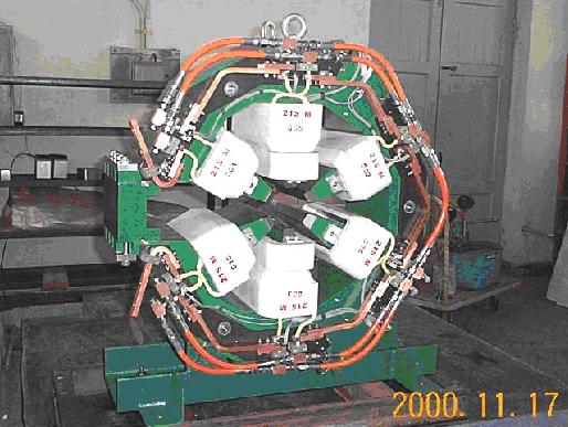
All three prototype magnets are currently in SLAC magnetic measurements shop to establish the relationship of the magnetic center to the mechanical center and to document the alignment values of the fiducials. The quadrupole and sextupole magnets (see picture below) are being measured using the rotating coils fabricated by IHEP and sent to SLAC. These coils are used to confirm IHEP measurements and spot check production magnets as needed.
34Q Quadrupole prototype measured at SLAC
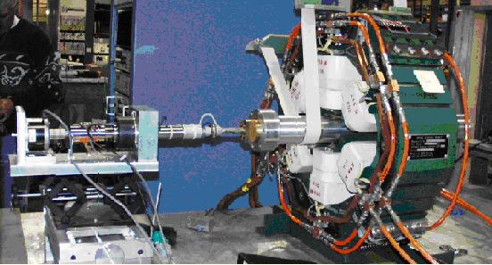
Prototype Sextupole with Compensated Rotating Coil being
measured at SLAC
Compensated Line Integral Coil Measurements at SLAC
Corrector Magnets
The corrector magnet design was reviewed in early October
with no major issues. During the IHEP visit in October, the H/V Corrector
magnets were discussed and reviewed. Attachment #5 has been drafted and
is in circulation for review and signature. Seventy five (75) magnets will
be fabricated for the SPEAR3 project.
· Evaluate the type of copper used for the standard
girder chamber.
· Machine and weld a QFC chamber using ¼
hard Revere copper.
· Complete the EB weld tooling for BM-1 and BM-2.
· Build tooling to straighten the large BM-1 and
BM-2 chambers
· Assemble BM-1 and BM-2 chambers.
· Received 1st lot of Beam Position Monitors.
· Evaluate the optimum location for the SLM monitor.
· Layout the diagnostic vacuum chambers.
· Complete the prototype BM-2 Support detail drawings.
· Complete preliminary detail drawings for the
BM-1 and QFC supports.
Standard Girder Chambers
We received the second set of QFC chamber plates machined
from ¼ hard Revere copper in October. As discussed last quarter
the vendor found that the Revere material showed smaller deflections after
machining than the Outokompu ½ hard material. The second chamber
made from Revere material was assembled and welded following the same assembly
process as the first chamber which was made from Outokompu material.
The Revere plates were easier to straighten and the final box weld exhibited
smaller deflections than the Outokompu plates. The difference in
the yield and tensile strength of the two materials are small and it was
decided that the Revere ¼ hard material would meet the mechanical
requirements for the chambers. A material specification for the copper
was written and included a lower limit for the yield strength of the material.
Testing also showed that the Revere material met the requirements of OFE
copper class 2 or better.
A decision to replace the material for BM-1 and BM-2 was made after examining the results from the machining, assembly, welding, material testing and cost and schedule impact. The requisition for the ¼ hard material was placed this quarter. Due to availability and schedule the QFC chambers will be made from the existing ½ hard material. The assembly of the first two QFC chambers demonstrated that these chambers could be made from either Outokompu or Revere material, but the larger chambers would benefit from the ¼ hard material. The first lot of material is expected in the beginning of March 2001. The machining of the QFC chambers was restarted at the end of December and the 1st lot of halves is due in the beginning of March 2001. Also, an updated delivery schedule that is consistent with our production flow was proposed and tentatively accepted by the vendor.
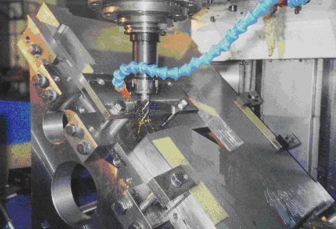
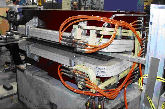
Assembly of the BM-1 and BM-2 chamber also started this quarter. Figure 2.1 shows the cooling bars and the machined halves installed in the tooling fixture. The welding of the cooling bars will start in January. A picture of the BM-2 chamber in the welder is shown in figure 2.2. Also, the design and fabrication of the tooling for straightening the long chambers is near completion.
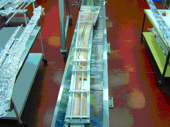
Figure 2.1: BM-2 chamber Cooling bar weld set-up
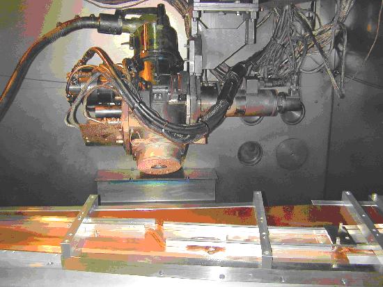
Figure 2.2: Electron Beam Welder BM-2 cooling
bar weld
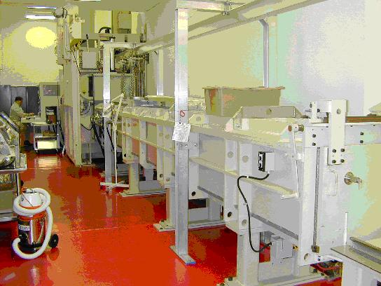
Figure 2.3: Electron Beam Welder
During the next quarter efforts are being made to establish the production workflow for the standard girder chambers. Additional managing staff was obtained from SLAC to help coordinate the production of the chambers. Also, additional technician staff was added to support production.
The piece parts for all the chambers will be placed this quarter. Final modifications to all the drawings are being made and should be complete by the end of January.
Beam Position Monitors
Forty-eight beam position monitors were received in December.
The destructive testing to verify the design and fabrication of the beam
position monitor will commence next quarter. The production inspection
procedures are being finalized.
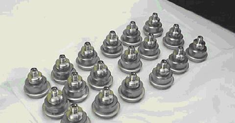
Figure 2.4: 1st lot of Beam Position Monitors for SPEAR
3
Standard Girder Supports
The detail drawings for the BM-2 prototype will be released
in January and submitted to the shops for fabrication. The remaining
drawings for the production QFC, BM-1 and BM-2 supports are near completion
and should be released by the beginning of February. The prototype
supports should be complete and ready for installation by March.
Injection Kicker
The parts for the injection kicker prototype assembly
will begin in January. Also, the higher order mode test apparatus
parts are on order.
Septum Chamber
The design for the septum chamber, mating transition
chambers, and septum bellows was completed this quarter. Models and
detail drawings are complete and ready for review. Integration meetings
were held with the magnet group to coordinate interface issues. A
status review will be held in the beginning of January. The final
design review of the chamber is pending the final design and analysis of
the septum magnet. Supports for the septum chamber are currently
being designed.
RF Straight Section Chambers
The designs for the RF straight chambers, transition
chambers, and RF bellows module are complete. The final design review
will be held this quarter pending any changes required for higher order
mode (HOM) issues. The HOM calculations should be complete by February.
The detail drawings for the RF bellows are in final check and the drawings
for the other components are on hold because of manpower issues. Revised
information on the mis-steering was received this quarter. Analysis
using both the angle and position mis-steer tolerance was evaluated to
determine if masks could protect the RF cavity flange pairs and bellows
modules. Masking of the bellows module could be achieved, but one
flange pair cannot be fully masked without encroaching on the beam-stay-clear.
The final decision on the RF mask is still pending. Also, other
lattice options for the RF straight are being studied. These mis-steer
cases have not been evaluated for the current vacuum system design.
Diagnostics
A decision on the location of the synchrotron light monitor
(SLM) was made this quarter. Numerous locations were examined to
determine the optimum location for the SLM that could meet the diagnostic
requirements and reduce the impact on the current and future beamlines.
A meeting was held with both beamline and storage ring physicists/engineers
to agree on a location. It was decided to use the ID port from girder 15.
Since the RF cavities utilize the long straight upstream of girder 18,
this ID port is the least likely location for a future ID beamline.
Also, the old control room in building 120 could house the optics table
for the SLM. Final optics and physics requirements are in progress.
Initial layout of the mirror and the cold finger mask has been done along
with thermal calculations.
Originally 17S18 was reserved for the SLM. Therefore, in order not to use two straights for diagnostic equipment, the vacuum group had to squeeze the remaining diagnostic chambers into the kicker straight and RF straight sections. The decision for the SLM allowed the vacuum group to move the remaining diagnostic equipment into 17S18. The initial layout and synchrotron ray tracing for 17S18 was completed this quarter. Detail designs of the scrapers, synchrotron light monitor and DCCT are in progress.
All 16 manufacturers were then contacted in an attempt to determine why they had declined to bid. Nine manufacturers stated no interest and they will not bid on the power supply because: a 930kW switchmode power supply is beyond their technical capabilities; some of the technical and/or performance requirements or the analysis needed to demonstrate compliance with the reqiuirements (e.g.; seismic, reliability or electromagnetic conformance) cannot be met; or their resources are not sufficient to take on a power supply of this complexity at this time.
On the other hand, seven manufacturers stated that they would be interested in the power supply under the following circumstances:
2. The power supply would be built in conformance to SSRLs specifications, but delay the power supply start date to June 2000. This late date was considerable unacceptable because this late start might put the power supply on the project critical path.
3. Configure the power supply as 4 parallel-connected AC controller power supplies or as 4 series-connected buck regulator power supplies. These approaches were rejected because line commutated AC controllers do not have the required bandwidth and the manufacturers total estimated cost for the 4 buck regulator power supplies was too expensive.
4. Configure the power supply in general conformance to the specification, but with 2 paralleled and 2 series buck regulators. Two manufacturers suggested this, but their estimated costs were considered too expensive.
1. Use the actual, measured dipole magnet resistance and efficiency from the measurements of the production magnets.
2. Evaluate the voltage and current margins in the power supply components under normal and worst-case operation.
3. Run a spare PEP II power supply under controlled conditions to determine the actual output rating limits.
Neeltran has resubmitted the Dipole Power Transformer electrical and mechanical drawings, incorporating SSRLs previous comments. The drawings will be reviewed for acceptance and for a release for fabrication.
Intermediate Power Supplies
During the next reporting period the specification for
the freestanding, intermediate (relative to the dipole power supply) size
power supplies will be developed.
Bipolar Power Supplies
The first prototype is expected to be complete by January
1st. A total of 12 power supplies should be finished by the end of February.
Testing will then commence using the Bipolar Power Supply Test Stand that
has been described in earlier reports. Byra, an assembler has been given
about 90% of the parts needed for the production run which should commence
by the end of March.
Kicker Pulsers
The entire set of machine parts for the core assembly
and high voltage feeds have arrived. After some minor rework the core assembly
has been assembled for fit. The ID specified for the cores was 4 inches,
but the vendor wound the cores on a 4 inch OD mandrel. The mandrel was
machined so that it would fit inside the core assembly, while leaving enough
mandrel material for mechanical strength.
Some minor rework of the circuit cards was also needed, but these have now been stuffed and successfully low voltage tested.
The coaxial cable arrived, so now all of the material needed to proceed with high voltage testing is now available. Prototype testing will begin in January.
Some progress has been made on the design of the enclosure for the modulator. The high voltage assembly has coax that is connected to both the top and bottom of the IGBT/core stack. The idea is to support the stack in a standard 19" rack with Unistrut. All of the cables between the modulator and the magnet would come through the top of the rack. The other components for the modulator, such as the power supplies, and controls would be standard rack mountable modules.
Precision Power Supply Controllers
As reported in the previous quarter, all of the critical
parts needed for the Bitbus-style controllers have been received and are
in storage. No further work on the controllers was planned during this
quarter.
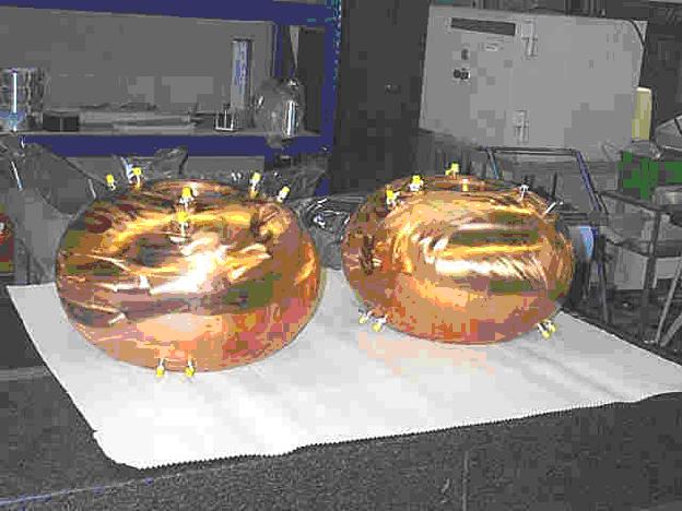
Fabrication of cavity accessories at SLAC including ceramic windows and higher order mode loads is making rapid progress. All twelve high order mode loads are completed. The ceramic windows had faulty first braze test, indicating a loss of the know-how at an external vendor. The braze is planned to be done in house at SLAC. Other components like tuners and coupling network are 90% complete.
Klystron
The 1.2 MW klystron was ordered March 17, 2000 from Marconi
Applied Technologies with a 12 month delivery time. The acceptance test
at the factory is now scheduled for the end of February 2001.
Waveguide
The waveguide layout design is complete and drawings
are signed off. A requisition for the circulator has been submitted to
the SLAC purchasing department.
Low-level RF
The Low-level RF System design modifications are in process
at the new Electronics & Software Engineering Department at SLAC.
Computer Control System
· The VxWorks operating system has been installed
on the first two Power PC modules and software development work is
commencing. A software development infrastructure has been configured
that permits remote access to the Power PCs and development software packages
and enables file transfers between multiple platforms over the network.
This system was used successfully to test the first two IF digital processing
modules (see below).
· Work is continuing on the design of the fast
digital power supply controller. A draft design for a mezzanine board
that carries the digital processing and control components has been completed.
The range of candidates for ADC and DAC functions has been narrowed and
evaluation boards for them will soon be tested. Detailed specifications
of the digital regulation and filter algorithms for power supply control
and monitoring are in progress.
Beam Monitoring Systems
· Studies of the two alternative methods for BPM
RF/IF conversion (4:1 switched button processing or parallel button with
4:1 switched BPM processing) are nearing completion. A design workshop
will be held in the next quarter to select which method will be used.
Then a decision will be made to pursue the design in-house or from an outside
vendor.
· The first 2 IF Digital Receiver modules from
Echotek have been tested and requests for design revisions have been accepted
by the vendor. Approval for production of the remaining 12 modules
has been granted.
· The BPM Timing/Crate Driver (T/CD) module design
is 95% complete and is on-hold until a decision regarding switched-button
or parallel-button RF processing is made. This decision will affect
the final configuration of the T/CD module.
· Development of the orbit feedback processing
algorithm is on-hold until the DSP engineer replacement is identified.
· The BESSY II mechanical design drawings for
the image current-carrying shroud for the DCCT have been reviewed.
A simpler design used at the Photon Factory in Japan is being considered.
· A location for the UV/visible light synchrotron
light monitor has been identified and the system design is in progress.
Timing System
· The PTS DDS-based signal generator that was ordered
to serve as SPEAR 3 RF master oscillator has not been received yet.
· Work on specifying the LO/Clock and Booster-SPEAR
Phase-Locked Loop systems has been on hold given that the new engineer
assigned to the task has had other higher priority responsibilities.
The specification is planned to be completed during the next quarter.
Protection Systems
· A decision to eliminate the Access Control Interlock
search areas in the East and West shielding areas is pending the detailed
design plan for a new building to be constructed at the West shielding
area.
· A preliminary design review of the Orbit Interlock
was held in December. Several functional and design issues were identified
and will be addressed as the detailed system design progresses. A
key issue is whether the rf signals from BPM buttons can be divided between
the Orbit Interlock and precision orbit monitoring processing systems without
significantly degrading the performance of the precision system. The present
analysis indicates that the signal division is acceptable. If future
tests show that there is a problem, it may be necessary to install redundant
BPM electrodes in the vacuum chamber so that each processing system has
its own signal.
Concerning cable tray design, the details of outdoor tray and supports are largely defined. A top-level layout drawing with sections and installation details exists and is continually updated. Additional pieces of the plan were developed after the completion of new shielding alcoves at both East and West pits. The tray in these areas can now be supported directly from the alcove roofs using short supports.
Within Building 118, supports which will increase the load bearing ability of the roof, are under design. These supports are needed when the roof trusses must carry both SPEAR2 and SPEAR3 cable loads. Originally conceived as temporary, the supports are now planned as permanent, since the supports provide desirable structural enhancement, do not interfere with equipment occupancy, and de-installing them only increases cost.
A design for upgrading the East-West elevated cable trays to incorporate four new 30 wide cable trays was completed to the conceptual level. In order to carry the increased load, seismic retrofitting of the columns and piers is required. A design for the retrofit was completed and was approved by the Seismic Committee. The cost of the approach is being evaluated for comparison to the cost and suitability of using existing underground cable ducts. The ducts are lower capacity than the overhead trays, and would increase the cable lengths.
A decision on the tray or duct approach is forthcoming and will allow production of drawings for a final design review. The drawing package for a portion of the tray work, including the East-West run, and trays inside Building 118, will be ready for bidding early this year. The installation work is planned for shutdown 2001.
Management of the Cable Plant has shifted to the SLAC Controls Department. This was done in order to increase the allocated manpower and provide particular expertise in cable plant design. Leading the effort will be Mr. Robert Fuller, who becomes the WBS 1.6 System Manager. Mr. Fuller will be assisted by Mr. Mario Ortega. In addition, the participation of the SLAC Cable Group, which has been involved in SPEAR3 since the beginning of the project, has been formalized. Also, the drafting, documentation, and Quality Control sections of the Controls Department have been formally assigned a SPEAR3 Cable Plant role.
The engineering and design drawings for the remaining cast-in-place concrete shielding walls and the pre-cast roof shielding in West Straight Section are in progress and scheduled to be completed in January. The pre-cast roof shielding will be designed to support the RF Waveguide assembly and the lead shielding around the penetrations. The construction will start in July and be completed at the end of September 2001. The remaining cast-in-place concrete shielding wall in East Straight Section and the roof shielding will be installed in the summer 2002.
The engineering and design drawings for the Utilities modification are now 70% complete and scheduled to be completed in February. The various accelerator maintenance groups will further define the lighting placement and requirements of the AC distribution before the design is finalized. The work is scheduled to start in July of this year.
Accelerator Simulator
The first version of the Accelerator Toolbox (AT) is
complete and has been released for use within SSRL and at other national
laboratories. The toolbox contains code for particle transport through
basic elements (drift, dipole, quadrupole, sextupole, rf cavity) and a
series of computational tools (orbit, betafunctions, tracking, etc). Physicists
at LBL report that the AT toolbox executes faster than previously used
codes and have suggested minor modifications that have been incorporated
into the first release.
Additional software is being added to include 'mapping' functionality in the AT toolbox. Mapping allows the physicist to represent propagation of a particle beam distribution through the transport line as a high-order Taylor series in the 6-dimensional phase space. Mapping was used for long-term tracking in the SSC and finds applications to synchrotron light sources, for instance computation of closed orbits without iterative numerical search. The mapping portion of the AT toolbox takes advantage of MATLAB links to the 'ZLIB' C++ library developed at SLAC. The new software is will expand the range of computational capability for SPEAR 3 physicists and bring the more complicated 'mapping' technology to a more useable level for physicists at other national laboratories. The new software will be used to teach mapping techniques at the USPAS accelerator school in Texas this coming January.
Application Programs
The ORBIT application program has been revised to speed
execution and operate online with SPEAR 2. Successful tests were carried
out December 12 to demonstrate orbit correction in the MATLAB application
program using Simple Channel Access (SCA) acquired from LBL. Both the SCAGet
and SCAPut (parameter retrieval and set functions) functioned satisfactorily
in the online setting. The demonstration of a MATLAB application program
and use of SCA meet a major SPEAR 3 accelerator physics milestone set for
December 20, 2000. The ORBIT software is also in use at the CAMD accelerator
in Louisiana.
SPEAR 3 Matching Cells
The SPEAR 3 matching cells are used to adjust the periodic
optics in the main arcs of the accelerator to the long straight sections
that will house the RF cavities and future beamlines. To ease engineering
constraints and reduce production costs, the innermost sextupoles (SFI)
were moved 7 cm toward the center of the cell. This allowed the vacuum
group to use the same design for the central matching-cell chamber as is
used in the standard cells (QFC). The cost reduction is captured in both
ED&I and fabrication.
A slight modification was also made to re-locate quadrupole QFX 5 mm closer to QDY in order to re-use the corrector design for the standard cells.
Studies of photon beam mis-steering have begun for the matching cells to provide masking specifications to the vacuum engineering group. Since the matching cells have shorter dipoles (3/4-length) and higher betafunctions at some locations, the potential for beam mis-steer is higher in the matching cells. The accelerator physics and vacuum engineering groups are working closely together to finalize masking specifications.
Synchrotron Light Monitor
Extensive studies and negotiation with the SSRL beamline
engineering group have resulted in an agreement to locate the synchrotron
light monitor optical bench in the building 120 room presently used for
BL 1,2 controls. The synchrotron radiation will be taken from the BM2 dipole
on girder 15 and exit through the ID port that would otherwise service
an ID 15S16. Since 15S16 contains the septum and K2 kicker, no insertion
devices are planned. The BL 1,2 control room provides a sealed enclosure
with water, power and compressed air for the synchrotron light monitor
diagnostic. Further studies are needed for radiation shielding considerations
where the light beam exits the main shielding wall.
Diagnostics Straight
The main SPEAR 3 electron beam diagnostic components
(tune drive/monitor, scrapers, DCCT) and PPS stoppers will be located in
the 4.8 m long straight 17S18. A preliminary layout is complete and operational
parameters have been specified. A study is underway to determine if we
can install two transverse kickers (one horizontal, one vertical) that
will initially operate as low-power tune drivers but can be used as high-power
transverse feedback kickers at a future date. The basic design would be
patterned after the PEP-II/ALS transverse kickers. The tune receiver will
be BPM buttons. The DCCT module will be ordered from Bergoz, Co., and encased
in a shroud modeled after BESSY-II. The scraper modules will be custom
designed for SPEAR 3 applications. A set of BPM buttons will be installed
at each end of the 17S18 straight.
Dedicated leading edge
A mask in the RF straight will protrude past the nominal
30 mm horizontal beam-stay-clear and past the 25 mm septum radius to accept
the beam power load during beam abort. The 'leading edge' mask/dump will
be located in the RF straight and penetrate to approximately 22-23 mm radius
in the horizontal. By locating the mask/dump inside of the septum radius
we can protect the thin septum blade against a 1.2kJ energy impulse when
RF is cut at 500 mA/3GeV. The mask/dump will also intercept most of the
particles lost in the horizontal plane during the natural decay of the
beam. Particles lost vertically will go to the small gap insertion devices.
The horizontal mask/dump will receive most of the stray charge during injection.
Prototype magnet measurements
The accelerator physics group worked with the magnetic
measurements group to certify acceptance tests for the prototype dipole,
quadrupole and sextupole magnets from IHEP. Following a minor chamfer modification
on the quadrupole magnet to reduce the n=6 multipole component, all of
the magnets exceed specification. Tracking simulations with measured multipole
content verify the result.
Low betatron function studies
Discussions were held with the future beamline study
group to identify lattice requirements for future beamlines in SPEAR 3.
Based on these discussions, a preliminary study was made to form a double
vertical waist in the 7.6 m East straight to accommodate two insertion
devices. The result showed the optical configuration is possible (with
additional magnets in the future) but further study will be required to
maintain dynamic aperture at the present level.
The Preliminary Safety Assessment Document (PSAD) has slipped behind schedule, however, we still anticipate a draft document out before the next quarterly report.
Work continues on the near term radiation physics objectives
that will have an effect on this years shutdown, as well as long term goals
to comprehensively assess all shielding and design parameters, thus assuring
that respective regulations and internal limits are met. Ongoing work includes
defining what additional shielding may be required for the new C shaped
dipole magnets and minimum thickness of roof shielding for areas around
the ring.