April
through June
2000
|
TABLE
OF CONTENTS
A. Project Summary B. Detailed
Reports 1.2 Vacuum
System 1.3 Power
Supplies 1.4 RF
System 1.5 Instrumentation
& Controls 1.6 Cable
Plant 1.8 Facilities |
A. SPEAR
3 PROJECT SUMMARY
1. Technical Progress
“The
project team has made very good progress on the development of designs
for the technical components and conventional facilities. This was especially
true for the vacuum system. The accelerator design has matured as indicated
by the thoroughness of accelerator physics analysis of the SPEAR 3 design.
The magnet systems team was congratulated for a large volume of excellent
planning and design. The magnets and girders appear to be sound and the
production schedule looks quite realistic. There were some concerns by
the committee that the girders do not have adjustable supports, and that
the storage ring would require additional maintenance time to keep the
ring aligned. In the areas of Power Supplies, RF Systems and Instrumentation
& Control all appear to be moving along well and show evidence of close
collaboration between SSRL and SLAC, which recently completed the PEP-II
project successfully. The project presented an installation plan to the
committee that had everything installed in eight months rather than the
six months allotted by the shutdown schedule. Adequate time remains to
work the installation schedule to allow for the appropriate planning and
staging of technical components, and to adjust to the new funding profile.”
“The
management structure and dedicated staff are in place to effectively execute
the project. The team has implemented a Project Management Control System
(PMCS) that was used on the PEP-II project. The project management understands
its ES&H responsibilities. They are aware of ES&H policies and
have implemented them to ensure ES&H is integrated into the planning
of activities, and hazards are identified, evaluated and integrated.”
The
new funding profile noted above was provided to the project subsequent
to the review on June 21. We are in the process of establishing a new cost
baseline and associated schedule in accord with the new funding plan.
The
technical progress for this quarter is summarized below with details in
Section B.
In
the magnet program, the prototype dipole unit was completed and ready for
magnetic measurements in April. Nanyang Li, SPEAR 3 magnet engineer, traveled
to IHEP to oversee the final assembly phase and end-pole chamber details.
Magnet group leader Richard Boyce together with Domenico Dell’Orco and
Jack Tanabe visited IHEP in May to witness the final product and the results
of the magnetic measurements. The IHEP measurements indicated that the
field quality measurements were met. The prototype dipole was shipped on
June 5 and arrived at SLAC July 6. Additional measurements will be made
at SLAC to confirm the field quality of this first unit. The tolerances
of the dipole laminations were verified previously and punching of laminations
for production units is in progress.
The
first laminations for the quadrupoles were received at SLAC in late June.
Measurements here confirmed thatthe
dimensions were well within the specified tolerances and approval was given
to proceed with production of the laminations. Both dipole and quadrupole
achievements are meeting the project schedule for magnets that was established
last year.
The
first machined top and bottom halves of the QFC vacuum chamber were received
from the manufacturer in June. Tooling is near completion for production
e-beam welding at SLAC which is planned for late July. The first machined
components for the BM1 and BM2 units of the arc-raft chambers are also
scheduled for July. Much effort is being devoted to the supports of these
chambers which are in very close proximity to the magnet supports in most
cases. Vacuum system designs are also underway for photon stops, titanium
sublimation pumps, kicker magnets, insertion devices, and various bellows.
A
purchase order was placed in April for the 1200 KVA dipole power transformer,
which is actually two 600 KVA units in one enclosure. A successful design
review for the overall dipole power supply was held in May. The goal is
to have all design specifications ready for bid proposals in July. A design
review was also held in May for the induction kicker magnet supply. Parts
have been ordered and fabrication of the prototype unit will begin in August.
The
order for four PEP-II style RF cavities and one PEP-II 1.2 MW klystron
were placed last quarter. The cavity production in on track. Sample aluminum
halves of the cavities were machined to verify lathe programming and the
machining of actual copper cavity half sections has been initiated. Qualification
samples by the manufacturer to verify the procedural steps are nearly complete.
Efforts are in progress to improve the high voltage power supply design,
the low level RF system, and the detailed design of the wave-guide system.
In
the Instrumentation and Controls department, work has advanced on the specification
and design of the computer control system, beam monitoring system, RF master
oscillator, and the orbit interlock system. Work continues on cable plant
details and schedule adjustments have been made to meet the requirements
of the new funding profile.
Intensive
efforts continued this quarter to finalize drawings and specifications
for construction of new shielding walls and access mazes in the East and
West straight section areas. The work is scheduled to begin July 7 with
completion by mid-September. Contractor site walk-throughs took place in
early May with bids required in mid-May. Unfortunately, only one contractor
responded. The award was made in June at a price 450K$ above budget. This
will result in the second CCB action for the project.
The
accelerator physics group has focused on control system application developments.
This has included graphical/interactive orbit control programs, fast feedback
system simulations, pinhole camera development for vertical emittance measurements,
and development of field uniformity requirements for vertical corrector
magnets.
DOE/OAK
has reviewed and approved SLAC’s equivalency request and find hazards analysis
for SPEAR 3. The installation ofa
new Very Early Smoke Detection Apparatus and the on-site fire department
provide an appropriate level of fire protection as required by DOE Order
420.1.
2. Cost Reporting
| Table 1
Project Costs (K$) through June 2000 |
||
| Direct | Direct plus
indirect |
|
| Costs | 5,422 | 6,323 |
| Commitments | 6,864 | 7,447 |
| Total | 12,286 | 13,770 |
Table
2 provides the BCWS, BCWP, and ACWP with associated cost and schedule variances
through this reporting period. The variances are increasing as we are still
reporting against the planned schedule and milestones for a plan for completion
in FY 02. A new funding profile was provided by DOE on June 21 (following
the Lehman Review) which provides additional funds for project completion
in FY 03. We are in the process of establishing a new cost and schedule
baseline which we will be tracking against in the coming months. The next
quarterly report will reflect this revised project plan.
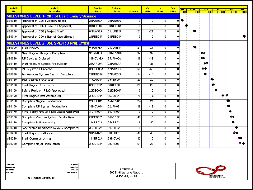
Table
3 provides a list and baseline schedule of Level 1 and Level 2 milestones
for the project. All milestones scheduled for completion prior to the end
of this report period have been successfully completed.

Figure 1
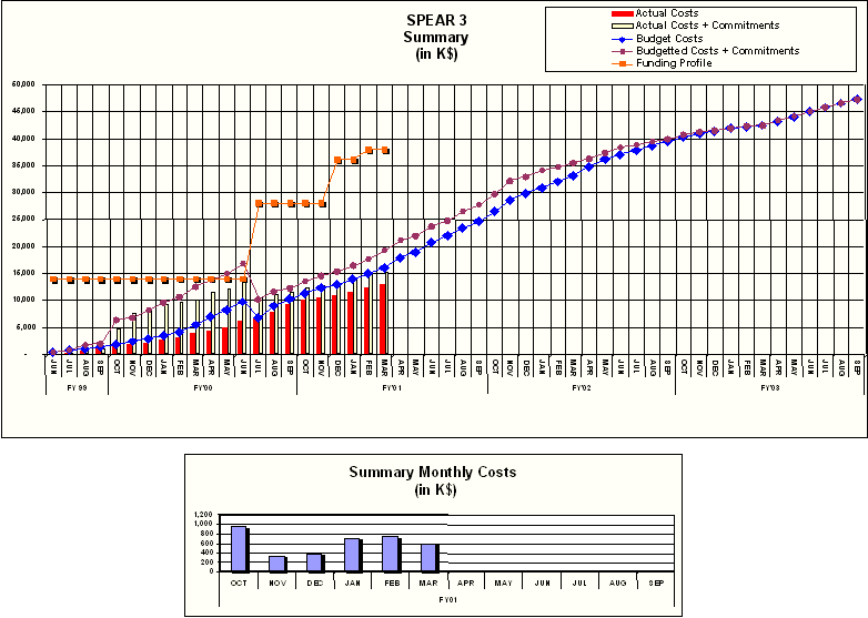
Figure 2
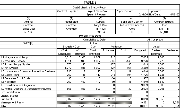
Table 3
B.Detailed
Reports
Supports System

Figure 3. SPEAR3 Standard Cell Girder
The support system designs have been ongoing. The
preliminary review of SPEAR 3 magnet supports was held at SLAC on June
21, 2000. The girder design is being modified to allow for the new layout
of vacuum chamber supports. The purchase order for support rod ends of
dipole, quadrupole and sextupole prototypes has been issued.
The
Lehman Review held on June 13-14, 2000 concludedthe
following: “The SPEAR 3 team is to be congratulated for a large volume
of excellent planning and design. The magnets and girders appear sound
and the production schedule looks quite realistic. The decision to use
three girders per sector is a good one and will facilitate installation.
The fact that the girders do not have adjustable supports adds some risk
that extra ring maintenance time will be needed to keep the ring aligned,
especially since a new floor will be poured just a few weeks before the
start of girder installation. However, the compensatory benefit is that
the SPEAR 3 girder is extraordinarily rigid, with all vibrational resonances
above 20 Hz in frequency.This should
be very beneficial for orbit stability. The six-strut system of magnet
supports will minimize the added effort necessary to re-level the ring
by moving every magnet”.
Magnet
SLAC shipped to IHEP the first batch of water fittings
and hoses to be used for the production magnets. IHEP and SLAC solved the
technical problems experienced during the soldering of water fittings to
the copper conductor and the Devcon injection in the dipole laminations.
IHEP has begun punching the dipole laminations for the production magnets.
The
revised design of quadrupole magnet 34Q-3 was introduced to allow the installation
of the vacuum pump port at the QF1, QFZ-A and QDX-B locations. IHEP completed
the drawings of all the dipole, quadrupole and sextupole magnets variations.
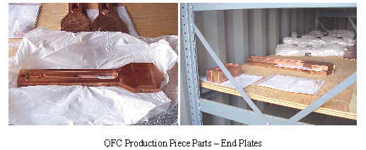
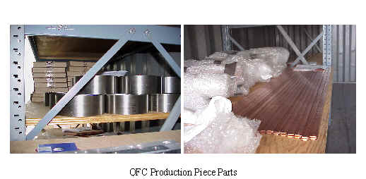
Figure 4. End view and back
view of the gradient dipole magnet. Pictured are the LCW manifolds and
hoses, bus connections between the upper and lower sets of coils, and terminals
for thermal switches and trim coil connections.
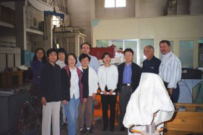
Figure 5. Group picture of IHEP magnetic measurements group and SLAC in Beijing
Magnet measurements
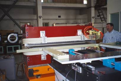
Figure
6. Translating coil setup for the magnetic measurements at IHEP
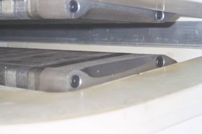
Figure 7. Close-up view of the chamfered pole insert for the 145D prototype
The 2D field quality results obtained with the Hall
probe are in very good agreement with the 2D Ansys calculations and within
the SLAC specifications for good field (DB/B
< 2 ´
10-4 at 30 mm from the beam and 3 GeV).
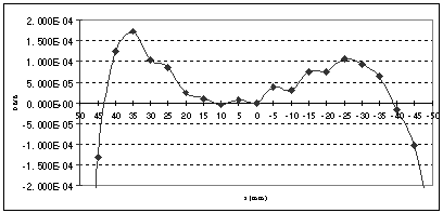
Figure 8. 2D Hall probe measurement results: DB/B < 2 ´ 10-4 at 30 mm from the beam (-46.6 mm < x < 46.6 mm) at 630 A and 3 GeV
The
integrated field quality measurements performed with the translating coil
were used to iterate the profile of the chamfered pole inserts. The second
iteration in chamfer profile met all the magnetic field specifications
issued by SLAC.
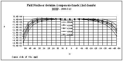
Figure 9. Compensated translating coil measurements results. The average value of DB/B along the beam trajectory(-46.6 mm < x < 46.6 mm) at 630 A - 3 GeV is less than2 ´ 10-4
IHEP manufactured 2 rotating coils that will be used in the magnetic measurements of quadrupoles, completed the quadrupole die and punched 3 test laminations. The CMM measurements performed by IHEP on the quadrupole laminations met SLAC specifications and the laminations were sent to SLAC for confirmation.
1.2 Vacuum
System
¨ Integrate standard chamber design and supports and complete the standard girder chamber design details,
¨ Complete the detail design of the assembly/electron beam (EB) welding tooling,
¨ Complete fabrication of the QFC chamber assembly tooling and start the fabrication of the BM-1 and BM-2,
¨ Begin first article fabrication of the QFC chamber,
¨ Complete the conceptual design of the standard girder vacuum supports,
¨ Continue TSP testing,
¨ Complete the conceptual design for the injection kickers,
¨ Start the design of RF cavity straight chambers,
¨
Continue work on the conceptual design of Beamline 11 (BL11) transition/bellows
module.
Work
has continued on completing the standard girder drawings.All
of the piece part and assembly drawings are in final check and work on
finalizing the documentation is near completion.Also,
design and detail drawings of the electron beam welding tooling for all
the standard chambers are complete.The
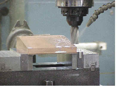
QFC EB weld tooling was fabricated this quarter and the BM-1 and BM-2 EB
weld tooling will be complete next quarter.Due
to the new 3-D parametric modeling system and the delay in producing an
operational database system, a temporary release procedure is in use.Setting
up a manual release system has led to delays in releasing drawings.
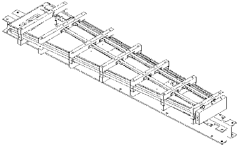
Figure 10. QFC EB Weld Tooling
Also, design and detail drawings of the electron beam
welding tooling for all the standard chambers are complete.The
QFC EB weld tooling was fabricated this quarter and the BM-1 and BM-2 EB
weld tooling will be complete next quarter.Due
to the new 3-D parametric modeling system and the delay in producing an
operational database system, a temporary release procedure is in use.Setting
up a manual release system has led to delays in releasing drawings.
The
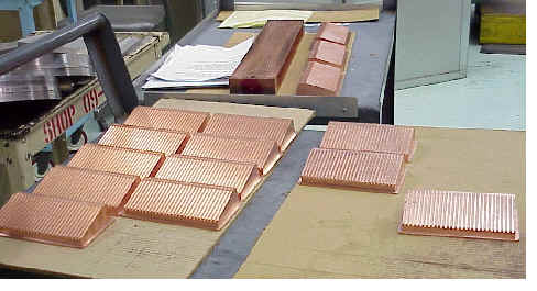
majority of piece parts to produce the QFC vacuum chamber were received
this quarter.The machine halves
were received in early June.After
the chamber halves were dimensionally inspected, they were assembled with
the sidewalls using the EB tooling fixture.Measurements
of the assembled chamber were taken to provide systematic information of
chamber deformation during each assembly stage.This
information will help define the assembly procedure and potentially eliminate
some of the fabrication steps.During
the next quarter, the remaining fabrication steps will be performed with
systematic inspection data. Currently a mechanical straightening fixture
is being developed and the plates will be straightened before any welding.Two
sets of plates for the BM-1 and BM-2 machined halves are currently being
machined and are expected to be delivered to SLAC in July and August.
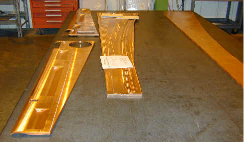
Figure 11. Production Machined Plates
Delivery
of the SPEAR3 beam position monitors (BPMs) is approximately 2 months behind
schedule.The vendor had difficulty
locating the stringer free copper-nickel alloy.Also,
the company relocated their manufacturing facilities from Colorado to Connecticut.The
change in the production facility and some staff has led to delays in the
manufacturing of the BPMs.SLAC has
provided their purchasing experience to help locate the material.The
SPEAR3 project also changed the sequence of welding the BPMs into the standard
chambers to minimize the impact on schedule due to the late delivery.
Significant progress was also made during the last
quarter on the supports for the standard girder chambers. The compact
magnet lattice required close integration between the vacuum, magnet and
girder designs. Several iterations of the vacuum chamber supports
were required to create a design that could meet the space constraints.
The conceptual design and structural calculations were completed and a
conceptual design review was held on June 21, 2000. The conceptual
design was approved and work on the action items and finalizing the design
will continue through next quarter.
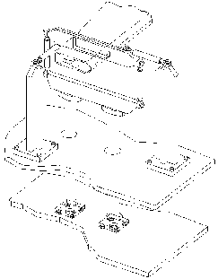
Figure 12. Standard Girder Support
Pump testing on the conceptual design of the titanium
sublimation pump demonstrated that the titanium sublimation coverage was
less than anticipated. This lowered the capacity of the pump and
decreased the time required between titanium sublimation. A simple
modification was made to the pump to increase the surface area and line
of sight for sublimation of titanium. Detail drawings and fabrication
of a new TSP was completed this quarter and testing will start next quarter.
Further design changes may be required in order to meet our design goals.
A conceptual layout of the RF straight was completed this quarter.Ray trace studies were performed and mask locations were defined based on estimated acceptable values for synchrotron radiation deposition.Analysis on the masks and pumping are pending.Conceptual designs for the higher-order mode drifts and the RF mask/pump module are near completion.Also, the conceptual design and analysis of the RF bellows module was completed.
Work on the insertion device transition modules were put on hold this quarter to shift manpower to the standard girder chambers.Some progress was made earlier in the quarter to finalize the conceptual design of the BL-11 mask-transition-bellows module.Design and analysis work should restart late next quarter.
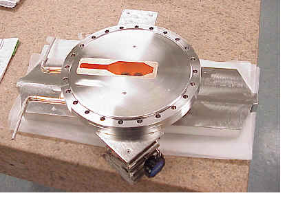
Significant
progress was made on the injection kicker design.A
conceptual design review was held on May 17, 2000.The
vacuum group presented the vacuum/magnet design of the kicker for the 1.2-m
and 0.6-m long DELTA style kickers.Impedance
and magnet calculations were performed and the design was optimized.The
design review resulted in approval to build a prototype 1.2m long injection
kicker.The prototype magnet will
be built by September 2000.Detail
drawings for the injection kicker are in progress.
DOE/NIH June 13th and 14th Review
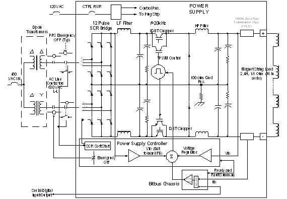
A successful design review for the Dipole Power Supply was held on May 24th. No major problems surfaced and the buck regulator topology (shown in Figure 14) was accepted as proposed. However, several minor issues did arise. These review issues are being investigated/resolved and those that are appropriate will be incorporated into the Dipole Power Supply Specification that is currently in preparation. The goal is complete the specification and have it suitable for bid purposes by the end of July. Industry is also being canvassed in an attempt to locate potential manufacturers that are qualified and have the capability and interest to design and fabricate the rather large 930kW Dipole Power Supply.
Bipolar Power Supplies
During the next quarter, work will begin on the fabrication and testing of 8 prototype bipolar power supply boards. A comprehensive test series is planned, focusing on electrical and response performance, thermal performance, EMI spectral analysis and crosstalk immunity.
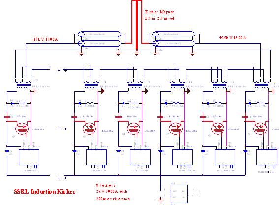
Kicker Pulser
Considerable modeling of the kicker magnets and the pulsers has been done with the PSPICE circuit analysis program. Below is a PSPICE generated waveform of the current in the K2 kicker magnet. The displayed current pulse has the required amplitude and shape.
Single Channel Power Supply Controllers
Figure
13. Dipole Power Transformer
Outline
Figure
14. Dipole Power Supply Topology
Figure
15. Mutichannel Controller
Eurocard Crate In Certification Test Stand
Figure
16. Induction Kicker Pulser
Schematic Diagram
The new RF system layout using a single high power
klystron driving the 4 RF cavities is being finalized. A new location for
the klystron and controls part of the RF station was chosen within the
building covering the West-Pit. This location greatly simplifies overall
RF system layout by bringing the klystrons close to the chosen cavities
position in the tunnel. A new 2MW klystron power supply will replace the
standby existing 860 kW power supply. The pre-installed klystron, control
electronics and power supply can be commissioned early while SPEAR 2 is
still in operation.
A Change Control Board (CCB) review was held and the
new CCB#1 was approved. With this action the new RF system layout and the
new klystron location were accepted.
Fabrication of 4 RF cavities at Accel Instrumentation
in Germany is making good progress. The process qualification samples are
essentially complete including the machining of the cooling channels in
an aluminum model. Preformed copper bowles for the cavity body have been
provided by SLAC and the inner and outer contours have been machined. The
next process is the joining of two cavity halves by an equatorial weld.
(Delivery of the cavities is scheduled for Fall 2002). Fabrication of cavity
accessories at SLAC like ceramic windows and higher order mode loads is
about 90% complete.
The 1.2 MW klystron was ordered March 17, 2000 from
Marconi Applied Technologies with a 12 months delivery time. This company
is also providing the replacement klystrons for PEP-II. The associated
waveguide layout design is 90% complete and drawings are expected to be
signed off next quarter.
The Low-level RF System was reviewed and design modifications
have been started. A modification to the Ripple Feedback Loop in the main
RF module is also being considered for a PEP-II upgrade. Several chassis
like the Local Control Panel and the Tuner Driver Chassis have already
been built. The Process Logic Control system for interlocks and status
readbacks has been ordered and received. Component procurement for other
modules and chassis’ is under way.
1.5 Instrumentation
and Control Systems Work by the SPEAR 3 Instrumentation and Control (I&C)
group during this quarter has focused on the continuing specification and
early design of computer control, BPM processing, timing and protection
system components.Progress for various
systems is provided below.
·
Work is progressing on the design of the fast digital power supply controller.
ADC, DAC and CPU component candidates have been identified and ADC evaluation
boards have been ordered. Digital regulation and filter algorithms for
power supply control and monitoring will be specified in the next quarter
in order to select a CPU appropriate for the controller. Digital control
of the power supply pulse-width modulating units, which would eliminate
the need for DACs, will also be considered.
·
The BPM Timing/Crate Driver module will be completed after receipt of the
Digital Receiver module (to assure proper connector choices) and the first
unit is planned for fabrication in the next quarter.
·
An orbit feedback simulation model is being developed on MATLAB Simulink.
The ControlShell software development tool from RTI has been purchased;
ControlShell takes MATLAB model programs and generates VxWorks code that
actually implements feedback routines. The engineer responsible for this
work (and for Timing System components) has left SLAC and a replacement
engineer is being sought from within SLAC.
·
The BESSY II mechanical design for the image current-carrying shroud for
the DCCT will be adapted for SPEAR 3.
·
The design for the UV and visible light synchrotron light mirror has begun.
Progress
continues to be madeon
technical design of the Cable Plant, principally the cable tray design.Preparation
for shutdown FY 2000 work was completed. Details
of the enclosure Cable Tray design continue to be identified.The
cross-section of the standard cell, indicating cable tray and piping dimensions,
is being optimized.The Cable Tray
that carries water-cooled bus may need to be reduced from 6” to 4” height.To
determine the suitability of this change, the cable fill factor and electrical
codes are being reviewed. Cable
Tray material required for the standard-cell mockup was located on-site,
and installed in the mockup.Since
the amount of on-hand material was limited, an order has been placed for
the additional material.The cable
tray mockup is intended to exactly model the configuration to be used inside
the enclosure, including all width transitions, tray drops, and ground
wire bonds. An
upgrade of Equipment Cabinets (Relay Racks) in the SPEAR Main Control Room
(MCR) is underway.This is a SPEAR
infrastructure (Accelerator Improvement Project) upgrade that is essential
to SPEAR3.The project consists of
early removal of unused cables, increasing the size of the Control Room
work area, increasing available console space, modernizing the relay racks
with eleven new racks, and decreasing ambient noise.The
MCR is also receiving new general-purpose duplex outlets. This
improvement project was guided by inputs from the Operations, Accelerator
Development & Controls, and Accelerator Physics groups.Several
plans were developed and the best of these plans was selected for implementation. Phase
I of the improvement is being completed during shutdown FY 2000.In
Phase I three new racks are added, equipment relocated, and old racks decommissioned.The
racks and electrical supplies are ordered and are due in July.An
earthquake resistant support frame has been designed, peer reviewed, and
is in fabrication.Phase II is scheduled
for shutdown 2001.These infrastructure
improvements will facilitate the installation of SPEAR3 control electronics
in the MCR.
The
bids for the construction of the new shielding walls and mazes in the West
and East straight sections were opened on May 16th.
See the last quarter (Jan-March) report for layout drawings of the modifications.
The only bid submitted was 72% higher than the Engineer’s Estimate. A second
effort to invite more potential bidders to re-bid the project again resulted
with the same bidder from the first bid. The lack of interest from potential
bidders and the high bidding price are believed to be result of the fertile
economy in the San Jose silicon valley area.Subsequently,
the subcontract was awarded on June 3rd.The
project kickoff meeting was held on June 8th.The
construction is scheduled to commence on July 10th and be completed
on September 15th.The
engineering is at 100% completion and the design drafting is at 95% completion.
During the third quarter of FY 2000, efforts of the
accelerator physics group were concentrated on control system application
development and support for machine engineering issues.
Accelerator Simulator
Simple Channel Access
Figure
17. Graphical Orbit Control panel for SPEAR 3.
External Program Driver from MATLAB

Computer Control System
Beam Monitoring Systems
Timing System
Protection Systems
The
design of the Orbit Interlock has begun. A pair of BPM processors and associated
support hardware will be purchased for test from Bergoz, Inc. Interlock
processing CPU options are being considered, with VME-based PowerPC modules
being a likely candidate.
The
complete accelerator simulation library is being assembled in the format
of a MATLAB 'toolkit' (nominally a commercial product) to facilitate code
maintenance and sharing with sister DOE laboratories. A web site is under
construction to facilitate access to the code and provide information about
the code. Based on the underlying particle transport simulation modules,
higher-level physics applications have been developed. An example is the
coupled-lattice betatron function calculation based on theory developed
at Cornell.
This system will be tested on SPEAR 2 in the Fall of 2000.
Fast feedback simulations have been initiated in SimuLink (a MATLAB
tool box) to study corrector power supply stability and corrector field
uniformity requirements. The SimuLink studies have also begun to investigate
the use of modern control algorithms which achieve feedback performance
exceeding the standard '3-parameter' feedback technique used at most accelerator
laboratories. Initial results indicate the optimized algorithms out-perform
the standard techniques when sensor noise is present. The control algorithms
were then transferred to a commercial 'ControlShell' development environment.
ControlShell is intended to facilitate development and deployment of moderate-to-large
scale control systems such as the orbit feedback system for SPEAR 3. Studies
to determine the practical extent for use of ControlShell in the SPEAR
3 feedback system will continue into the next fiscal year.
