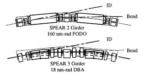
Figure 1: SPEAR2 and SPEAR3 magnet girders. |

SSRL is proposing to upgrade the SPEAR2 storage ring, which is itself an upgrade of the 2.4 GeV SPEAR1 ring which dates back to 1974. This upgrade, along with an upgrade of the synchrotron radiation beam lines, will significantly enhance the research capabilities of the Laboratory. By replacing the ring magnets and vacuum chamber (Fig. 1), the natural 3 GeV electron beam emittance of SPEAR3 will be reduced from the present 130 nm-rad to 18 nm-rad and the stored beam current will be raised from 100 mA to 200 mA. The injection energy will be raised from 2.37 to 3 GeV to eliminate energy ramping and its impact on orbit reproducibility. While it will be possible to ramp SPEAR3 to 3.5 GeV, the RF system, which will be reused with minor enhancements, will initially limit the maximum current at 3.5 GeV to about 75 mA. Careful optimization of the magnet lattice and vacuum system design should yield a beam decay lifetime of approximately 40 hours at 200 mA.
Figure 1: SPEAR2 and SPEAR3 magnet girders. |
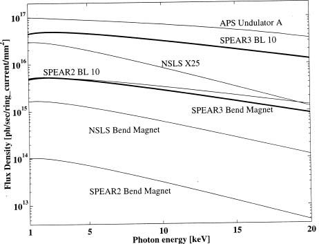
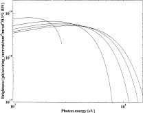
The smaller beam size (Table 1) and higher current in SPEAR3 will increase the focused photon flux densities for insertion device beam lines by an order of magnitude (Fig. 2). The photon beam brightness for future 4 meter undulators will exceed 1018 in the 5 keV range (Fig. 3). The new lattice has shorter bending magnets with a smaller radius of curvature, raising the critical photon energy from the present 4.8 keV to 7.1 keV at 3 GeV. The resulting bending magnet focused flux density at 20 keV will be more than two orders of magnitude greater than it is presently, and will be comparable (over the whole spectrum) to the focused flux density produced now by the BL10 wiggler. The higher photon beam power density and brightness will be accommodated by upgrading beam line masks, slits and windows, by installing LN2-cooled monochromators on most hard X-ray insertion device beam lines, and by improving mirror and other optical component performance. This will allow the SPEAR3 beam lines to take full advantage of the source improvements.
 |
Table 1: Electron beam dimensions at SPEAR2 and SPEAR3 source points with 1% horizontal-vertical coupling. |
A key feature of the SPEAR3 project is the minimization of the interruption of the SSRL's user program. This will be accomplished by limiting conversion downtimes to a series of normal 2-month shutdowns and one longer shutdown period of about 6 months. This concept has been the basis of the scope and planning of the SPEAR ring conversion. To minimize the amount of work that must be done in the 6-month down time, the new magnets will be mounted on existing support girders which, (with the exception of the four girders flanking the two long symmetry straight sections), will remain in place. Existing components such as magnet bussing, cabling, and water connections, will be reused wherever possible. Beam line alignment will remain unchanged except for a minor 5 mrad angular shift needed for each of the four bending magnet lines.
In the past several months considerable effort has been invested in designing the proposed lattice, maximizing beam lifetime, optimizing beam source point parameters, and developing component designs. The resulting design has required that a defocusing quadrupole gradient be added to each bending magnet and that the two bending magnets on each support girder must be moved apart to create room for sextupole magnets, making bending magnet beam line realignment necessary. Another consequence of lattice development is that the four magnet cells adjacent to the East and West symmetry straight regions will be moved towards the old colliding beam interaction points, lengthening four straight sections from 2.7 m to 4.5 m and providing two 8.5 m symmetry straight sections. While these developments benefit beam quality and enhance the potential for future insertion device development, they also increase the amount of work that must be done in the 6-month conversion period.
|
Figure 2: Focused flux density for several beam lines and the existing SPEAR source, the proposed SPEAR3 and beam lines from other existing synchrotrons |
|
Figure 3: Brightness curves for a 4 m version of an APS Undulator A installed on SPEAR3 |
A high degree of beam stability is crucial for exploiting the low emittance beam properties of SPEAR3. Limiting beam motion to small fraction of its transverse dimensions implies that electron beam position for focused beams or for highly collimated undulator beams should be stable to the order of 20-40 µm rms horizontally and 5-10 µm rms vertically. Angular stability should be <10% of the photon beam opening angle, characterized by 1/g = 170 mrad at 3 GeV; this divergence is reduced by a factor of 10 for an undulator having the order of 100 periods, implying microradian stability will be needed for this type of source. To attain these stability requirements, magnet girder and optical component vibration will be suppressed, thermally induced motion of ring and optical components will be minimized, and feedback systems will be used to attenuate orbit disturbances and transverse coupled bunch instabilities. A longitudinal multibunch feedback system will also be used to reduce energy oscillations induced by vacuum chamber and RF cavity impedances that can spoil beam energy resolution.
The accelerator upgrade portion of the SPEAR3 project is being planned as a 3-4 year project, beginning as early as FY 99. The beam line upgrades will take place over a 5-year period, beginning as soon as FY 98. Special funding for the project is being sought from the DOE. All beam lines will be operational at the end of the 3-year accelerator conversion, although another year will be required for monochromator improvements on several insertion device side stations. With future funding, the Beamline 4 and 7 electromagnet wigglers can be replaced with permanent magnet devices similar to the one used for Beamline 9. By upgrading the RF system and increasing the power handling capacity of the beam lines, the SPEAR3 operating current could be increased to as much as 500 mA, thereby taking full advantage of the capacity of the new vacuum chamber.
 |