Draft by J. Schmerge (6/00)
At this time the highest operational repetition rate for a 1.6 cell RF gun has been 50 Hz [] at 100 MV/m. Thus there is a possibility of damaging the RF gun if it is operated at the 120 Hz repetition rate of the LCLS due to excessive heat loading. There are two ways around this problem. The first is to study the energy deposition in the rf gun and provide appropriate cooling at the necessary locations without compromising structural integrity. The second is to reduce the amount of energy being lost in the walls of the gun. Both methods have been investigated and the results are briefly described below.
To be supplied by X.-J. Wang.
Alternatively, one can attempt to reduce the amount of energy lost on the cavity walls and thus the required cooling also decreases. The cavity is designed to operate as an efficient accelerator. Thus the cavity losses are kept low to maximize the accelerating voltage in the gun for a given klystron power input. However, because the gun cavity is operated as a standing wave structure, the filling time becomes large as the losses decrease. Thus, when one uses the minimum necessary klystron power to drive the cavity, one must wait several time constants before the cavity voltage builds up to the required field level for normal operation. Since the field builds up exponentially, there is a relatively long time spent at field levels just below the desired operating field level and this results in a large amount of energy being dissipated as heat in the cavity walls. However, if a higher power klystron were used, the cavity could be filled to the desired field level in a much shorter time period. In fact a sufficiently high power klystron could fill the gun in an arbitrarily short time. Once the cavity is filled, the klystron power can be quickly reduced to the steady state value necessary to maintain the cavity at the desired field level. The rapid change in klystron power can be achieved using a fast attenuator (100 ns or faster) at the klystron drive input line. Alternatively, a fast phase shifter could be used to achieve the same effect but due to the stringent timing jitter requirements of the injector it would be preferably to avoid changing the rf phase.
The dominant heating mechanism of the gun is due to the rf power dissipated in the cavity walls due to the finite conductivity. Other energy deposition and extraction mechanisms are negligible compared to the rf power since they involve considerably less energy than the rf fields. The stored energy in the cavity fields is 6.1 J while a 5.3 MeV, 1 nC beam only extracts 5.3 mJ of energy and the drive laser supplies around 0.5 mJ of UV energy which is largely reflected by the metal cathode. Thus both effects have a negligible effect on the energy lost to the cavity walls and can be ignored in this calculation.
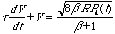
The amount of energy lost on the walls of the gun can be calculated from the cavity voltage and the shunt impedance. The shunt impedance is defined for a standing wave structure as R = 1/2 V2/Pwall where R is the shunt impedance, V is the cavity voltage and Pwall is the power lost on the cavity walls. The total energy lost to the walls is given by ºPwall dt. While it is difficult to measure the shunt impedance directly the cavity quality factor, Q0, can be measured either by time or frequency domain techniques and the shunt impedance is directly proportional to Q0. The proportionality factor is simply a function of cavity geometry and can easily be computed by field solver programs such as SUPERFISH. Q0 is defined as Q0 = w0U/Pwall where w0 is the resonant frequency and U is the stored energy in the cavity. The measured value of Q0 for the 1.6 cell RF gun installed at the Gun Test Facility is 12,400. The expected shunt impedance using the measured Q0 and the proportionality constant from SUPERFISH calculations is 1.7 MW/m. Finally the cavity voltage is calculated from the equation below where b is the rf coupling coefficient and Pk is the available klystron power. The equation assumes that there is no beam loading and the gun is operated on resonance.

The solution to the equation for a step function klystron drive pulse is also shown. The figure below shows the voltage as a function of time for two different klystron drive powers. In order to achieve the desired 5.3 MV accelerating voltage (110 MV/m peak field at the cathode) only 8.5 MW of RF power is required. The voltage builds up exponentially with a time constant of 600 ns and then is held constant for 100 ns before the end of the rf pulse and then exponentially decays. Assuming 120 Hz operation, the average power dissipated by the gun cavity under these conditions is 2.1 kW. Thus a gun operated at 50 Hz would dissipate roughly 0.9 kW.
However, if a 20 MW klystron were used for the first
600 ns and then the output power dropped to the 8.5 MW level for 100 ns
before the end of the pulse, only 0.65 kW of power would be dissipated.
Using this technique, the existing 50 Hz gun cooling would be sufficient
to operate the gun up to 160 Hz. Of course no klystron produces a perfect
step function output but the additional heat loading due to the rise time
of the klystron is small because during the rise time the cavity voltage
is still relatively low. Thus, for a 200 ns rise time, the additional power
dissipation is less than 0.1 kW. Likewise there is no significant additional
benefit from using a similar method on the trailing edge of the rf pulse
because most of the trailing edge is spent at low field levels where there
is minimal power disipation.
