
|
Stanford Synchrotron Radiation Laboratory |
|
Electrical System Group |


|
Microchip® 16 Bit ESG Development Web Page |

|
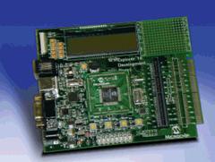
Proposal: Use low cost 16 bit, Microchip microprocessor to manage, diagnostic and control sub-system in SPEAR3 accelerator machines. This module describe the development environment using MPLAB ICD2 and Ethernet interface. |
|
Team: Fernando Rafael — x4607 John Wacther — x4217 |
|
Resources: MPCLAB C30 V2.02 — Documentation and download MPLAB ICD2 — Documentation Explorer 16 Development Kit — Documentation Ethernet PIC Tail Daughter Board — Documentation MCHPTCPStack 3.30 — Download (Thanks to W. Woodrow) AN833 — The Microchip TCP/IP Stack — Documentation Linksys WRT55AG — Specification |

|
SPI |
|
USB |
|
Ethernet 10 BaseT Full |
|
Ethernet 10 BaseT Full |
|
Microchip |
|
RS232 |
|
Configuration: Microchip TCP/IP Stack Definitions — File: StackTsk.h //#define STACK_USE_SLIP //#define STACK_USE_IP_GLEANING #define STACK_USE_DHCP //#define STACK_USE_FTP_SERVER (works only in EEPRON Mode) //#define STACK_USE_SNMP_SERVER //#define STACK_USE_TFTP_CLIENT #define STACK_USE_ANNOUNCE
#define MY_DEFAULT_IP_ADDR_BYTE1 (10) #define MY_DEFAULT_IP_ADDR_BYTE2 (10) #define MY_DEFAULT_IP_ADDR_BYTE3 (5) #define MY_DEFAULT_IP_ADDR_BYTE4 (15) #define MY_DEFAULT_MASK_BYTE1 (255) #define MY_DEFAULT_MASK_BYTE2 (255) #define MY_DEFAULT_MASK_BYTE3 (255) #define MY_DEFAULT_MASK_BYTE4 (0) #define MY_DEFAULT_GATE_BYTE1 (192) (Router Address) #define MY_DEFAULT_GATE_BYTE2 (168) #define MY_DEFAULT_GATE_BYTE3 (1) #define MY_DEFAULT_GATE_BYTE4 (1) #define MY_DEFAULT_MAC_BYTE1 (0x00) (MAC Address TBD) #define MY_DEFAULT_MAC_BYTE2 (0x04) #define MY_DEFAULT_MAC_BYTE3 (0xA3) #define MY_DEFAULT_MAC_BYTE4 (0x00) #define MY_DEFAULT_MAC_BYTE5 (0x00) #define MY_DEFAULT_MAC_BYTE6 (0x00)
MAC Module (Microchip ENC28J60) for Microchip TCP/IP Stack — File: ENC28J60.c // Since the ENC28J60 doesn't support auto-negotiation, full-duplex mode is // not compatible with most switches/routers. If a dedicated network is used // where the duplex of the remote node can be manually configured, you may // change this configuration. Otherwise, half duplex should always be used. //#define HALF_DUPLEX #define FULL_DUPLEX Works with WRT55AG //#define LEDB_DUPLEX
Pinout cross connection ENC28J60 J3 Pictail --> Explorer16 J5 Pictail PLUS RC4_ETH_SO (Pin10) --> RF7/SDI (PIN5) RB2_ETH_INT (Pin23) --> RE8/INT_1 (PIN18) RC5_ETH_SI (Pin8) --> RF8/SD0 (PIN7) RB3_ETH_CS (Pin21) --> RD14/U1CTS_E (PIN19) RB3_ETH_SCK (Pin12) --> RF6/SK1 (PIN3) RB5_EE_Reset(Pin17) --> RD15/U1RTS_E (PIN19) GND(pin28) --> GND(pin9) Notes: Don't forget to select correct PIC Voltage 3.3 V for Explorer 16. |
|
Setup Mode: Open Terminal application, and configure the serial port connected to the Explorer 16 board: • 19200 bps, • 8 data bits, 1 STOP bit and no parity • no flow control Apply power to the board while holding the S4 switch, or press and hold both the RESET and S4 switches; then, release the RESET switch. The LCD display shows the message on LCD: MCHPStack v2.0
|